How a compression gas spring works
The piston is pushed forward by the gas.
It is designed to set and regulate the speed of the rod exit.
Application example: Lowering, tilting and damping of sashes.
Detailed operation:
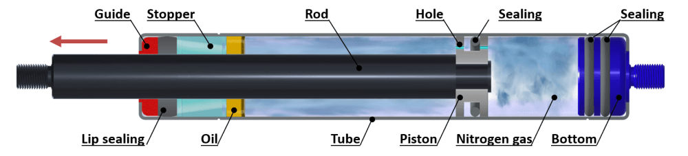
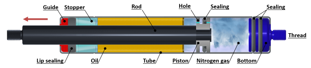
The compression gas spring consists of a cylindrical, watertight body called the Tube and a steel Rod at the end of which is mounted a Piston, which performs cycles of compression and expansion inside the tube. The Tube contains pressurized Nitrogen and a small quantity of Oil.
During the compression phase, the Gas flows from the right to the left side of the Piston through the Piston Orifices. At this point, the pressure inside the Tube rises, generating an increase in force.
The flow of Gas can be modulated by adjusting the diameter of the Orifices, in order to regulate the speed at which the Rod leaves the cylinder.
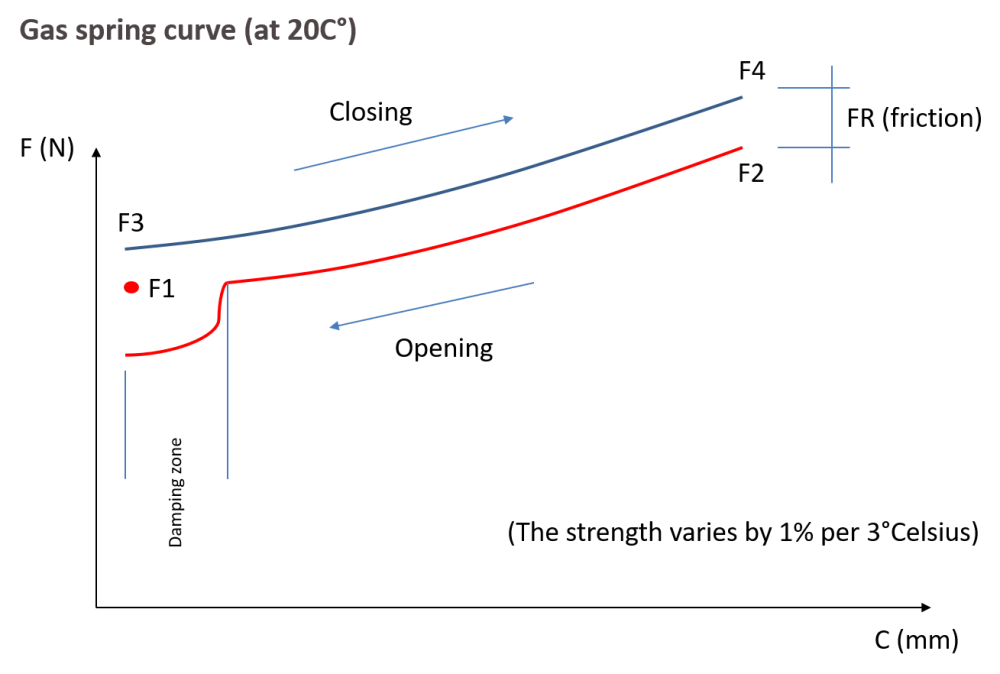
The rate of progression (also known as stiffness) can be modified by acting on the diameters of the Rod/Body pair and on the quantity of Oil (see force diagram below).
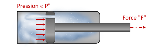
| Determination of a FORCE:
Force = Pressure x Surface (DaN) (bars) (cm2 of piston) (1 DaN = 10N) (P Max 160 bars) |
Mariotte’s law:
Pressure x Volume = constant (with CONSTANT temperature) P in Pascal (100 000 Pascal = 1 bars) V in M3 |
 |
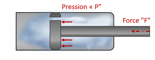 |
| Volume increases therefore pressure and force decreases | Volume decreases therefore pressure and force increases |
How a damper gas spring works
The piston is pushed forward by the gas.
It is designed to set and regulate the speed of the rod exit.
The cushioned cylinders include an oil charge of 65% of the internal volume. These gas springs cushion the rod extension at a speed of around 0.1 m/s. Rod retraction is free. Caution: inflation force is greatly reduced.
How a traction gas spring works
The piston moves toward the bottom of the cylinder under the effect of pressurized nitrogen.
This results in a pulling motion on the rod.
Application example: Lifting a hatch by pulling on it instead of pushing it.
Installing a gas spring in an application
Please note that the more information you have, the more accurate and therefore efficient the gas spring will be.
First of all, it is necessary to know the environment in which the gas springs will evolve : temperature, dust, aggressive environment, food etc..
The dimensions of the moving part (RH and LH) and the Weight to be lifted should be taken into account when choosing the diameter of the gas spring rod and the type of end fitting (environment, frequency of use, operator etc.).
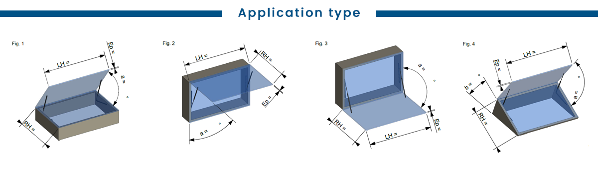
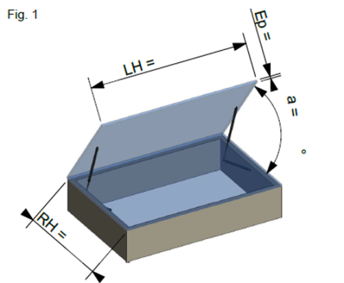
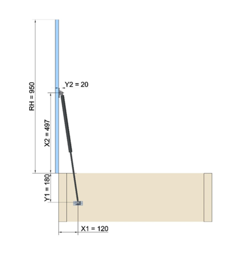
Case study with Fig. 1• Application type: Floor hatch – Ground level trapdoor (Most common) • To open a door with a 90° opening angle, the following rule must be observed: Stroke = 1/3 of RH Exemple: • RH = 950mm, LH = 1500mm, Weight = 30Kg, Opening angle = 90°, No of gas springs • We can use the reference: ST 300 +F1+ D10
Important: All the dimensions are taken from the axis of rotation • On the frame: The dimension Y1 will be less than the stroke, X1 will give the gas spring the necessary angle to the lever arm to start the movement, an ideal position will give an angle of 15° to 25° to the gas spring when the door is closed.
The dimension X2 will be defined by the extended length of the gas spring and the maximal opening angle. Y2 will take into account the thickness of the door as well as the type of fixing bracket chosen. In this example: X2 = 497mm, Y2 = 20mm If all the parameters are accurate, the hatch should be closed with is own weight.
|
|
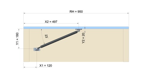
 *Les côtes sont exprimées en mm
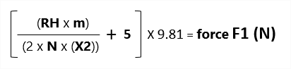
Force calculation
To calculate the force F1 of a gas spring in these two cases, the following formula should be applied:
- N= No of gas springs, RH= in metres, m= Weight in Kg, X2= in metres 5*= Friction force
- You can use our website to do this operation: http://dev.bertholdmarx.com/en/force-calculator
Adjust the force at upper tolerance:
F1 = 30 < N < 50 Add +0N
F1 = 50 < N < 250 Add +20N
F1 = 250 < N < 750 Add +30N
F1 = 750 < N < 1500 Add +60N
F1 = 1500 < N < 3000 Add +150N
F1 = 3000 < N < 6000 Add +300N
Browse our gas spring catalog and request a quote today!